FAQ

Frequently
Asked
Questions

Edit Content

The MonoLED is supplied with a USB interface acting as a shutter emulator to provide on/off control. To utilize this functionality, follow these steps: 

  • Download the MonoLED USB drivers from our support page and unzip the folder. 

  • Plug in the USB connection and direct Windows to the recently downloaded drivers. The device should now be recognized as a ‘USB Serial (UBW-based) communications port.’ Make a note of the COM port number allocated. 

  • The LED can now be digitally switched on or off in the following software packages using the appropriate hardware drivers (ensuring the correct COM port is assigned): 

    - MicroManager: Vincent-D1 

    - MetaMorph: Uniblitz Shutter Device 

    - NIS Elements: Vincent Associates Shutter


If you have any issues or questions, please contact us at tech@cairn-research.co.uk.

Yes, it’s fairly straightforward. The main thing to consider is that both the diameter and radiation solid angle of the LED chip will be greater than a 100-micron fiber can accept, so some light loss is inevitable.

However, a significant amount of light will still get through.

Since the illuminated area at the fiber’s output end will be smaller, the brightness should be comparable to direct illumination.

While attaching the fiber directly to the LED is possible, it is often more practical to focus an image of the LED onto the entrance of the light guide, making it easier to optimize performance. We can supply the necessary components to achieve this. 

A “white” LED typically consists of a blue LED with a peak around 445 nm, coated with a broadband phosphor centered in the green section of the spectrum.

Part of the blue emission from the primary LED is absorbed and re-emitted at lower energy by the phosphor. This combination of blue primary and green/red secondary emission appears white to the human eye.

Variants of white LEDs include: 

  • Cool white
  • Neutral white
  • Warm white


Each of these reflects an increasing red output from the phosphor. 

For fluorescence applications, both the primary (blue) and secondary (green/red) emission bands can be used, but the longer wavelength band will require a relatively broad excitation filter. 

The OptoLED can switch wavelengths in approximately 100 nanoseconds, which is effectively instantaneous for biological measurements.

The OptoLED Lite has sub-millisecond performance, which is sufficient for most applications. 

OptoLED: 

  • Controls two LEDs independently
  • Provides a very stable optical output via optical feedback
  • Can be pulsed on and off extremely rapidly (~100 nanoseconds)
  • LED intensity control via continuous current variation or high-frequency current pulses (or a combination of both)


OptoLED Lite:
 

  • Also controls two LEDs
  • Designed for less demanding applications (no optical feedback or high-frequency pulsing)
  • Operates over a wide current range
  • Has switching times of a few microseconds
  • Ideal alternative to quartz halogen lamps for general illumination but still suitable for many quantitative measurement applications
Edit Content

Yes, chromatic aberration is a frequently encountered problem with the Optosplit, but actually the cause is in the microscope, specifically the objective! 

It’s all to do with “longitudinal magnification,” which is a potential problem with any high-magnification system such as a microscope.

Longitudinal magnification is the SQUARE of the lateral magnification, and this has potentially nasty consequences!!!

Consider, for example, a x40 objective looking at a one-micron cube. 

Clearly its lateral size is 40 times bigger, i.e., 40 by 40 microns.

But to the extent to which the depth of field allows the image to be in focus more or less through its entire depth, then the size of the image in z is not 40 but 1600 microns!

In 3D we thus have a very elongated block instead of a cube.

Well, the chromatic aberration means that the focal length changes a bit across the wavelength range.

The focal length of the objective is given by the focal length of the tube lens divided by the magnification of the objective (of course!), and a change in focal length is basically equivalent to moving the object by the same amount.

But because of the enormous longitudinal magnification, the effect on the image is correspondingly greater. In other words, any chromatic aberration in the objective is ENORMOUSLY magnified.

For a 1:1 relay like the Optosplit, this effect just doesn’t happen, and for the lenses we use the chromatic aberration should be down at the diffraction limit anyway.

However, once you split an image between two wavelength ranges, the objective’s chromatic aberration hits you right in the face.

Especially true as you go out towards the red, where cameras see images far better than we do, and the objective’s chromatic performance tends to be getting worse in any case!

So, our corrector lenses act like “spectacle lenses,” to compensate for a problem elsewhere. They therefore need to be selected by straightforward trial and error!

And as for flatness of field, EXACTLY the same argument applies. A tiny error in the objective across the field is enormously magnified, and in practice will swamp any such errors in the relay.

So finally, this isn’t a specific problem with anyone's objectives! Everyone’s do it to some extent.

Customers who do accurate spectral scans have to use something like a PIFOC focuser to move the objective during the scan to compensate for all this!

There are several ways to achieve bypass with the OptoSplit II:

  1. Remove the dichroic cube, center the image with the split control, open the aperture, and adjust the trim control on the bottom to remove any vignetting. 

  2. Leave the dichroic cube in place, block the long-wavelength path with the shutter plate provided, center the image with the split control, open the aperture, and adjust the trim control on the bottom to remove any vignetting. 

  3. Leave the dichroic cube in place, block the short-wavelength path with the shutter plate provided, center the image with the split control, open the aperture, and adjust the trim control on the bottom to remove any vignetting.


This allows non-split mode using either filter in the Optosplit cube, or with neither in place. With a little practice, this bypass will only take a few seconds.

For smaller sensors, it may not be necessary to adjust the Trim control routinely, but we would suggest observing the effects of this control as it allows the beam separation to be optimized. 

The mirror coatings in the OptoSplit II are optimized to transmit visible light and in ‘bypass’ mode (following removal of the dichroic cube), transmission efficiency is an average 87% (across blue, green, and red emission).

If imaging low-light samples ‘full field,’ we would recommend removal of the Optosplit from the imaging path to maximize throughput. 

For the very best results, we would recommend using a 1X microscope C Mount (with no optics) and introducing the magnification in the splitter itself.

We do, however, have many customers who get excellent results from magnifying and demagnifying C Mounts and also using standard C Mount camera lenses.

If the two channels of your OptoSplit are not parallel, then it may be the case that you are adjusting the two channels using the wrong controls.

When the 2 channels are superimposed, you should only need to make adjustments using the split control and aperture controls.

If you are using the V1 and V2 controls to split the image along the vertical axis, it can result in the channels becoming misaligned.

If this occurs, you should refer to the manual to realign the OptoSplit. If you need a manual for an older version of the OptoSplit, then don’t hesitate to contact us. 

This is a routine application for the Optosplit, as the product has had provision for corrector lenses in one or other pathway since its inception.

This facility was originally provided for the correction of any chromatic aberration in the preceding optics but rapidly found a further application for deliberately defocusing one or other imaging pathway in order to allow different depths to be in focus at the same time!

Obviously, for z-plane splitting, a beam splitter is used rather than a dichroic. You may also be interested in our Optosplit III, which allows three different depths!

Cairn filter cubes accept standard 25mm diameter emission filters.

We strongly recommend the Chroma ET range to maximize levels of light transmitted.

For dichroic beamsplitters, we recommend 26mm x 38mm x 2mm (for other sizes, please get in touch with us, and we will be happy to advise).

After extensive testing, we only recommend Chroma 2mm thick ‘Ultra-Flat’ dichroic mirrors for minimal image distortion across all of our image splitter range. For more technical detail, see our Chroma Filters and Beamsplitters page.

For any filter or mirror advice (not limited to image splitters), please get in touch as we are UK stockists for Chroma – we are happy to help!

Both models are designed for two-channel image splitting on a single camera, but the OptoSplit II Bypass model has a simple lever to switch between split mode and single-channel operation.

By introducing a bypass mirror into the pathway, none of the splitter controls are moved, so there is no need to realign when you return to split mode. In addition, we use longer focal length lenses for improved image quality and use magnetically held cubes for improved registration.

Optosplit II Bypass Misalignment

A lesser degree of misalignment can occur if you turn the split control clockwise when splitting the image along the horizontal axis.

The OptoSplit II is designed to work optimally when the split control is turned anticlockwise. 

OptoSplit II Controls

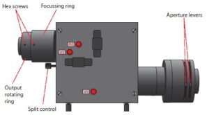
Here is a diagram showing the controls for the most recent OptoSplit. Older versions may have different control names, but all the controls are located in the same place.

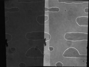
The rough edges in the image are a classic case of dirt on the aperture blades and can be remedied by cleaning with a lint-free lens tissue.

Edit Content

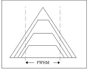
The Cairn OptoScan Monochromator has both an entrance and an exit slit, each with independently adjustable widths.

  • The exit slit width defines the bandwidth only if the input beam size is zero. The maximum exit slit width allows for a 30 nm bandwidth. 

  • In reality, the input light beam has a nonzero size, and its width is limited by the entrance slit width. 

  • The maximum entrance slit width is matched to the maximum exit slit width, ensuring any central wavelength ray within the accepted beam passes through.

    - Since the exit slit width allows a 30 nm spread, the entrance slit width is also limited to 30 nm. 


Key Considerations:

  • Fig. 1 (below) illustrates how passband shapes change as slit widths are adjusted. The Full Width at Half Maximum (FWHM) remains 30 nm, but the spectral profile varies. 

  • For light-limited fluorescence imaging, there is no practical benefit to setting different widths for the entrance and exit slits, as the improved spectral profile does not compensate for reduced intensity. 

  • If the application is not light-limited, a smaller entrance slit may be useful for tighter bandpass characteristics.


Software control:

- The OptoScan software allows users to set the center wavelength and adjust the slit widths.

- Some software versions include a "bandwidth" parameter, automatically setting both slit widths simultaneously—this option is recommended when available. 

Fig. 1:

Fig1 Illustrating Passband Shapes Changing as Adjusted

The OptoScan is optimized for narrow bandwidths, so we recommend arc lamps with high point intensity for the best performance.

We offer two 75W lamps, both with high point intensity, making them suitable for monochromators:

  • Ushio 75W lamp:

    - Ultra-stable, ultra-bright

    - Long-life (1500 hours)

    - Recommended for demanding applications 

  • Osram 75W lamp:

    - Less expensive alternative 

    - Shorter life (400 hours)

    - Still provides good monochromator performance


Recommendation:

Always keep a backup lamp in the lab in addition to the one in use.

These lamps are normally held in stock and available through our sales team.

Edit Content

Please follow the following procedure:

  1. Check that the bulb is well within its rated lifespan. The published figures are guidelines only, so although a 400-hour lamp will usually last 500–600 hours, if a bulb does fail at 300 hours, it probably just needs replacing. 

  2. Disconnect the power cable from between the lamphouse and the power supply. Inspect the cable thoroughly at both ends, and if any of the pins have become unseated, push them back and ensure that the cable is free from stress when replaced. 

  3. Taking care to wear protective eyewear, remove the bulb from the arc lamphouse following the instructions supplied with the system (copy available on this website).

    Clean the insides of both electrode holders with some fine sandpaper (even a small amount of corrosion can cause striking problems). 

  4. If the steps above don’t work, then either contact us to arrange for a return, or if you would prefer to try to avoid this, then it is worth widening the spark gap between the coils by a few mm. This gap provides an alternative route for the high voltage to bridge in the event of a failed bulb.

    Over time, the impedance across the bulb can increase, and the required size of the gap needs to increase slightly to ensure that the path of least resistance is still across the electrodes in the bulb and not the safety spark gap.

    To widen the gap, either snip the end off one of the wires or bend it slightly to increase the gap between the tips.


Spark Gap Illustration for OptoSource Lamphouse

This does sound like a faulty power supply. Please contact us to arrange to have it returned and checked out.

Please do not discard the “faulty” bulbs, as they may well function correctly when the power supply has been repaired.

Brand new lamps are easier to strike, so if the fault is marginal, it can appear to be an issue with the bulbs.

Edit Content

Yes. Cairn can provide ferrules for light guide coupling or design mounts for direct fit light sources.

For laser coupling, optics can be customized as needed.

Edit Content

All AT and ET filters have sputtered coatings with square-wave passband shapes, high transmission levels, high out-of-band blocking, and lifetime warranties. 

  • AT Series: Designed for routine fluorescence detection and assays but without the zero-pixel shift performance of the ET filters. 

  • ET Series: Provide zero-pixel shift performance with steeper transition slopes, allowing excitation and emission filters to be placed closer spectrally. This results in brighter images better matching fluorophore peaks.

Yes, Cairn keeps stock of popular microscope cubes and fits new sets as standard.

Alternatively, they can remove glued-in filters from old cubes, clean them, and refit new filters for a small fee.

Edit Content

Electron Multiplied (EM) cameras are particularly valuable for low-light applications, especially when signals are changing rapidly. 

For example:

  • A scientific cooled digital camera might deliver acceptable signal-to-noise images at 10 frames per second. 

  • An EM camera can increase the frame rate up to 100 frames per second, improving performance in fast imaging scenarios.

In certain configurations, the Cairn CellCam Camera may fail to shutter the light source, causing it to remain on after Live Mode is stopped.

Solution:

Update your drivers to the latest versions available from our support page of our website.

Edit Content

The OptoSpin25 and OptoSpin32 are fully supported in the following software packages via USB control:

  • MicroManager

  • MetaMorph / MetaFluor

  • NIS Elements


For other software packages, the OptoSpin position can be controlled externally using TTL high signals from an appropriate data interface. 

Alternative Control Method (TTL)

We provide a breakout cable with BNC connections, which requires:

  • 3 TTL highs to encode the stepping position (via encoded bits)

  • 1 TTL high to step the wheel (labeled GO)


This configuration allows control of two filter wheels from one power supply using 7 TTL highs (as the GO command is for both wheels simultaneously). 

The control lines are identical for both OptoSpin25 and OptoSpin32.


Additional Hardware Support

We commonly use a NIDAQ (National Instruments) card and driver to generate these signals.

Any Dig I/O interface that is compatible with your imaging software can also be used.

We can supply the National Instruments interface if required.

Learn how we helped 100 top brands gain success